Motion Control Solutions for Medical & Optical Instruments

Tiered Precision Micro-Motion Control, Low-Interference and Quiet Operation for Clean Medical and Optical Processes

Medical & Optical Instruments

Industry technical challenges

Wide variation in micro-travel positioning accuracy requirements

Basic optical auxiliary stages require only ±5–10 μm repeat positioning; wafer-level imaging and microscopic diagnosis demand sub-micron accuracy of ±0.1–1 μm. Motor step angle alone does not equal system accuracy; mechanical backlash and transmission deformation reduce overall system positioning performance. Vague “micron-level” descriptions can mislead selection.

Micro-vibration interference affecting precision processes

Optical instruments are extremely sensitive to mechanical vibration; even minor vibration causes image jitter, ghosting, and scanning deviation. All motors inherently produce torque ripple and bearing vibration, which can only be suppressed to very low levels, not completely eliminated.

EMI as a system-level issue

Medical optical equipment integrates numerous precision sensors, optical probes, and signal acquisition modules. EMI is determined by driver PWM, cable shielding, grounding, and filtering schemes collectively. Replacing drives with low-interference servos alone cannot fully resolve interference; complete system-level EMC design is required.

Precision decay over long-term operation

Medical optical equipment typically involves extended low-frequency, small-stroke precision reciprocating fine-tuning. Encoder thermal drift, mechanical fatigue, and environmental temperature variation cause gradual positioning deviation; no equipment maintains permanent zero-degradation performance.

Working Condition

Stepper Motor System Applications

Suitable for basic optical auxiliary stages and medical auxiliary trimming mechanisms in medical & optical applications, including:
Micro open‑loop stepper: For routine optical trimming and auxiliary alignment, meeting ±5–10 μm basic micron‑level adjustment.
Precision closed‑loop stepper: For mid‑range optical scanning/inspection, improving accuracy to ±2–5 μm.
Critical limitations:
Stepper accuracy is limited to about ±2–5 μm with limited vibration suppression (>0.02 m/s²);
Not suitable for sub‑micron (±0.1–1 μm) core processes such as wafer‑level imaging or micro‑diagnostic procedures;
EMI suppression is limited; not suitable for high‑sensitivity sensing equipment.

Servo Motor System Applications

Suited for core applications such as fully automated microscopy, wafer scanning, and precision packaging in medical & optics, including:
Low‑voltage servo (24V/48V): With core advantages of low vibration (<0.005 m/s²), low EMI (Class A), and high accuracy (±0.1–1 μm).
Integrated low‑voltage servo: For compact optical equipment and portable medical instruments.
Technical features: Combined with high‑resolution encoders (≥17‑bit) and precision mechanical transmission to achieve sub‑micron positioning; system‑level vibration and EMI suppression meet stringent medical standards (ISO 13485 compliant); smooth start/stop without impact for high‑end diagnostic/optical equipment.

Tiered Technical Solutions

Industry characteristics & selection logic:

Solution 1: Micro precision open‑loop stepper – Basic micron‑level optical trimming

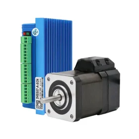
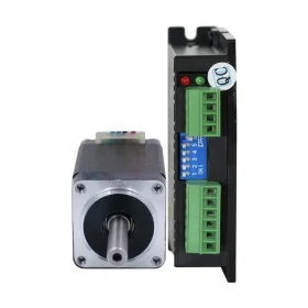
• Matched products 20J1840‑404 (0.027 N·m) or 28J1851‑407 (0.1 N·m) + 2DM415 (0.21–1.50 A, DC 18–36 V) • Applicable equipment Routine optical trimming stages (microscope stage coarse adjustment), small inspection alignment fixtures, medical auxiliary positioning equipment, light optical precision adjustment devices • Technical features Ultra‑high micro‑stepping (256), micro‑step angle 0.007° for fine, uniform small‑stroke adjustment; Low vibration (<0.05 m/s²), noise <38 dB; Compact for integration into precision equipment, stable under long‑term low‑frequency trimming; Repeatability ±5–10 μm – meets basic micron‑level auxiliary applications, not sub‑micron core imaging accuracy; ISO Class 6–7 cleanliness (low‑particle design). • Selection boundary Only for auxiliary coarse adjustment and alignment; core imaging axes (sub‑micron required) must use Solution 4 (low‑voltage servo).
medical-optical-instruments-solution-1

Solution 2: Precision closed‑loop stepper – Mid‑range micron‑level optical inspection upgrade

• Matched products 42J1848EC‑1000‑LS (0.5 N·m) or 57J1854EC‑1000‑LS (1.0 N·m, 1000 P/R) + 2HSS42 (0–2 A, DC 24–48 V) or 2HSS57 (0–5 A, DC 24–60 V) • Applicable equipment Mid‑range optical scanning/inspection equipment (confocal microscope scanning stages, non‑core imaging axes), high‑precision trimming stages, standard precision medical inspection instruments • Technical features 1000‑line encoder real‑time closed‑loop error correction, repeatability ±2–5 μm; Smooth, fine operation, low vibration and noise (<0.02 m/s², <40 dB); Eliminates long‑term micro‑stroke drift (<2 μm/24 h); Dynamic response and vibration suppression lower than low‑voltage servo (vibration ≥0.02 m/s²) – not for high‑end microscopy core axes; ISO Class 6 cleanliness. • Selection boundary Suitable for mid‑range inspection and auxiliary alignment; for high‑end microscopy (sub‑micron, vibration <0.005 m/s²), upgrade to Solution 4.
medical-optical-instruments-solution-2

Solution 3: EMI‑optimised closed‑loop stepper – EMI‑sensitive optical auxiliary

• Matched products 42J1848EC‑1000‑LS (0.5 N·m) + 2HSS57‑CN (low‑EMI closed‑loop drive with common‑mode choke and shielded terminals) • Applicable equipment Optical auxiliary equipment in EMI‑sensitive environments (non‑ultra‑sensitive sensors), medical inspection peripheral mechanisms • Technical features Enhanced EMC over standard closed‑loop, reducing radiated interference (conducted emissions meet CISPR 11 Class B); Accuracy ±2–5 μm; EMI better than standard closed‑loop but still below low‑voltage servo dedicated solutions; Suited for mid‑range auxiliary equipment with EMI requirements but not sub‑micron accuracy. • Selection boundary Suitable for auxiliary trimming in EMI‑sensitive environments; for core axes of high‑sensitivity sensors (e.g., electron microscopes, fluorescence imaging), use Solution 4 (low‑voltage servo).
medical-optical-instruments-solution-3

Solution 4: High‑end sub‑micron low‑voltage servo – Core optical imaging & diagnostics

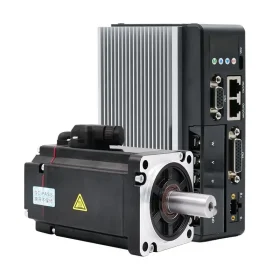
• Matched products 60ASM400‑5‑17BCH (48 V, 400 W, rated 1.27 N·m, peak 2.54 N·m, 17‑bit encoder) + MCAC610‑23B‑EC (EtherCAT low‑voltage drive, 10 A, built‑in EMC filter) • Applicable equipment Fully automated optical imaging (wafer inspection microscope Z‑axis/XY scan), precision medical diagnostic instruments (digital pathology scanners), multi‑axis optical inspection platforms, high‑end medical precision scanning equipment • Technical features Optimised torque ripple (<1% rated), system vibration reduced to <0.005 m/s² (with precision guides); Built‑in EMC filter (meets EMI Class A) with shielded wiring and proper grounding greatly reduces EMI (conducted emission below 30 MHz limit); Combined with 17‑bit encoder and precision transmission (ballscrew C3 or higher) for sub‑micron positioning (±0.1–1 μm); Only minor slow accuracy drift over long operation (<0.3 μm/24 h), recoverable by regular calibration; Noise <38 dB, ISO Class 5 cleanliness; Bus‑based multi‑axis coordinated motion for complex scanning paths (jitter <1 μs); Selection constraint: For load >5 kg or higher thrust, upgrade to 750 W (80ASM750‑5‑17BCH, 2.38 N·m). • Selection boundary Core axes for wafer‑level imaging, micro‑diagnostics, and precision scanning must use this solution; auxiliary trimming may use Solution 1 or 2.
medical-optical-instruments-solution-4

Solution 5: Bus integrated low‑voltage servo – Compact precision optical drive

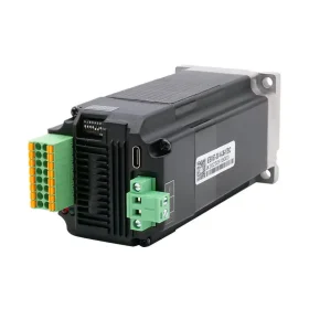
• Matched products IESV57‑30‑14‑36‑17BC‑EC (36 V, 140 W, rated 0.45 N·m, 17‑bit, EtherCAT) or IESV60‑30‑20‑36‑17BC‑EC (36 V, 200 W, rated 0.64 N·m) • Applicable equipment Compact optical scanning axes (portable inspection equipment mounting length ≤70 mm), precision alignment stage drives, multi‑axis optical inspection modules • Technical features Fully integrated drive, control, communication – minimal volume (axial length ~35 mm shorter than discrete); 17‑bit absolute encoder for sub‑micron accuracy (±0.1–1 μm); EtherCAT distributed control, sync <1 μs; Low vibration (<0.008 m/s²), noise <39 dB, ISO Class 5 cleanliness; Torque limit 0.64 N·m (peak ~1.9 N·m) – only for light‑load (≤2 kg) precision optical axes. • Selection boundary Suited for extremely compact, light‑load core optical axes; for load >3 kg or higher torque, upgrade to Solution 4 (discrete low‑voltage servo).
medical-optical-instruments-solution-5

Solution 6: Ultra‑low inertia non‑backpack integrated servo – High‑speed light‑load optical scanning

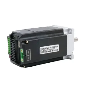
• Matched products IESV57‑30‑10‑36‑17BC (36 V, 100 W, rated 0.32 N·m, 17‑bit) or IESV60‑30‑20‑36‑17BC (36 V, 200 W, rated 0.64 N·m) • Applicable equipment High‑speed galvanometer scanning axes (light load ≤0.5 kg), fast auto‑focus mechanisms, high‑speed inspection scanning axes • Technical features Non‑backpack design, shortest motor length (≤60 mm) for extremely tight spaces; Ultra‑low rotor inertia (0.3×10⁻⁴ kg·m²), accel/decel <10 ms; 17‑bit encoder for sub‑micron positioning (±0.1–1 μm); Noise <37 dB, vibration <0.005 m/s² (with precision guides). • Selection boundary Suitable for high‑speed light loads (≤1 kg) with mounting length <70 mm in precision scanning; for load >2 kg or higher torque, upgrade to Solution 4.
medical-optical-instruments-solution-6

Technical Advantages

Clear accuracy tiering

Micro stepper for ±5–10 μm auxiliary, closed‑loop stepper ±2–5 μm for mid‑range, low‑voltage servo with precision transmission for ±0.1–1 μm sub‑micron high‑end imaging.

Multi‑level vibration and noise suppression

All series optimise torque ripple; low‑voltage servo offers best vibration suppression (<0.005 m/s²) and EMC filtering (Class A) – requires overall shielding and grounding for complete interference elimination.

Closed‑loop long‑term stability

Continuous micro‑displacement correction greatly reduces accuracy decay from thermal drift and mechanical fatigue (closed‑loop stepper <2 μm/24 h, servo <0.3 μm/24 h).

Low‑noise and clean‑room compatible

Vibration and noise optimised per tier (stepper <45 dB, servo <40 dB), meeting medical optical clean‑room standards (ISO Class 5–7).

Industry Application Cases

Basic trimming – Micro stepper for routine optical auxiliary equipment

For routine optical trimming, micro steppers with ultra‑high micro‑stepping provide fine, uniform adjustment with low vibration/noise – meet micron‑level auxiliary alignment at controlled cost; not for core imaging axes.

Mid‑range upgrade – Closed‑loop/EMI‑optimised stepper for optical scanning/inspection

Addresses long‑term micro‑drift in mid‑range scanning/inspection with real‑time compensation, improving repeatability to ±2–5 μm and reducing minor image jitter – not suitable for high‑end microscopy.

High‑end imaging – Low‑voltage servo for high‑end precision optical equipment

For high‑end imaging and precision scanning, low‑voltage servos achieve extremely low vibration (<0.005 m/s²) with system‑level EMC wiring for sub‑micron stable imaging – no ghosting, minimal data fluctuation.

Multi‑axis precision – Bus servo for medical precision diagnostic equipment

For multi‑axis medical diagnostics, bus servos provide smooth coordinated motion, precise action, and ultra‑low interference; regular calibration eliminates minor long‑term drift, ensuring long‑term inspection stability.

Ouote Request

Get a personalized quote tailored to your needs with our
quick and easy Quote Request Form.